Passive Solar Design Overview: Part 3 – Thermal Storage Mass

This is Part 3 in a series on Passive Solar Design by Will Stewart, a Systems Engineer in the energy industry and longtime reader of theoildrum.com. As a new administration considers how best to make future infrastructure investments, it seems like some of the lowest hanging fruit is better utilization of the daily solar flux, not only directly with photovoltaic and hot water, but also in building construction and placement. I encourage our readers to further their understanding of passive solar concepts by reading/bookmarking this series.
Underground house
Passive Solar Design Overview: Part 3 – Thermal Storage Mass

In Part 1 of this series, we looked at the three main architectural styles of passive solar design (Direct Gain, Indirect Gain, and Isolated Gain), as well as the first of the five design aspects, Aperture. In Part 2, we covered heat transfer, building heat gain and loss, and Absorbers. This article will present an over of the next design aspect, Thermal Mass, which is one of the main factors in avoiding passive solar overheating in the daytime and excessive cooling at night. Mornings are typically the coldest times for some passive solar homes, and this article aims to provide help to those who want to design their next home or renovate their existing one to provide moderation in heating, cooling, or both.

Overview

If the sun shone steadily upon our home or office 24 hours per day, we could simply size the equatorial-facing windows to collect just the right amount of sun for winter heating and be done. However, as the effective sunlight available in winter can be short-lived, in order to keep a reasonably stable temperature before the sun comes back up again, the passive building design must account for storage of warm thermal energy in the form of mass storage. The location, materials, shape, and size are the important aspects of mass storage (though shape is an advanced topic beyond the scope of this overview, as are detailed calculations of heat re-release via radiation and convection). Thermal storage techniques can vary widely between regions that tend to be closer to the tropics vs. regions that are closer to the poles. It should be pointed out that virtually all buildings have incidental mass storage in the form of furniture, wallboard, wood or masonry flooring, and so forth. This is usually not anywhere near the amount of storage needed, though with a superinsulation design approach it can supply an appreciable amount.

As noted in Part 1, passive solar techniques can be combined with active solar techniques; for example, a thermal mass floor heated directly by the sun could also be integrated (during the design/construction phase) with a radiant floor system heated on cloudy days by stored hot water from an active solar heating system.

Location of Thermal Mass

To review the 3 main styles of passive solar design, there is Direct Gain (sunlight enters through windows into the living space), Indirect Gain, and Isolated Gain.

    
Figure 7 - Indirect solar gain                                                      Figure 8 - Isolated Gain

There are also variants to these styles, with six examples below (many other variants exist);
  1. Interior wall mass storage: Interior walls, whether warmed directly by the sun part of the time or indirectly from reflections
  2. Standing walls: Similar to trombe walls, but are shorter and non-bearing, some providing a view out of the windows and easier access to insulating shades.
  3. External wall mass storage: Thick external masonry or log walls with little to no insulation that moderate swings in outside temperature in warmer climates where the average daily temperature is close to (or in) the 'comfort zone' (i.e., Southern California, Mediterranean, etc). Solar insolation on these external walls is also a factor, indeed a special case. Please note: in cool and cold climates, any thermal mass outside of the wall's insulation layer has little to no thermal storage effect in winter.
  4. Roof pond mass storage: A pond on the roof with thermal 'visibility' into the house, warmed during the day, covered with insulation at night [5]
  5. Earth mass storage: Partially (or fully) undeground house that uses the earth as thermal mass store.
  6. Annualized Geo Storage: An extension of simple earth mass storage (see figure 13). Hot air is collected year around and thermosiphoned down through a thermal mass wall in the winter (or via fan-driven bypass in the summer, making it active) and through the earth beneath a building [6].

Interior wall mass storage   Roof pond   

Figure 9 - Interior wall mass storage       Fig. 10 - Roof pond storage     Figure 11 - Standing wall storage


Sub-earth      Underground house
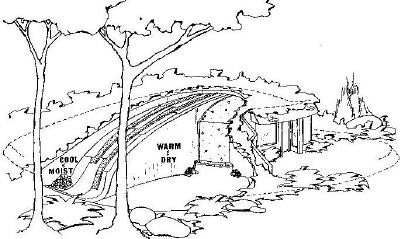
Figure 12 - Annualized Geo Storage                                        Figure 13 - Use of the ground for insulation and thermal mass


Thermal Mass Materials

Beside structural and aesthetic considerations, the main thermal mass properties we are interested in are;

  • specific heat (c): the amount of heat required to increase the temperature of a unit weight of material one degree. For example, it take 1 BTU to raise 1 pound of water 1 degree F.
  • density (ρ): the mass per unit volume for a material. For example, water weighs 8.33 pounds per gallon (lb/gal) or 1 kg/litre.
  • thermal conductivity (k): the rate at which heat travels through a material. For example, for each degree F difference between one side of a 1 foot concrete wall and another, heat travels through every square foot of that wall at 0.833 BTUs per hour (see value in Table 2).
  • thermal resistivity (r): the inverse of the conductivity.
  • heat capacity (β): specific heat times density (cρ), which determines how much heat energy a material can hold

Because we are EROEI-aware here at TOD, we also want to know how much energy was involved in the production and handling of the materials, called embodied energy. The values shown are approximates, as material hauling energy varies widely. Note that some of these values are often listed in other units (e.g., conductivity as BTU·in/hr F ft2) and careful attention must be paid to calculating units correctly (such as inches, feet, meters, cm, temperature scales, etc).

        Table 2 - Thermal Mass Properties and Embodied Energy of Common Materials
Material Specific Heat (c)
BTU/(lb F)
Density (ρ)
lb/ft3
Thermal
Conductivity
(k)
BTU/(hr F ft)
Thermal
Resistivity
(r)
(hr F ft)/BTU
Heat Capacity (β)
BTU/ft3/F
Embodied Energy
BTU/lb
Water (still) 1 64 0.351 2.941 64 0 (add energy to pump)
Face Brick
ASTM C 216
0.24 130 0.76 1.32 31.2 ~10752
Building Brick
ASTM C 62
0.22 120 0.47 2.13 26.4 ~10752
Concrete
(light)
0.22 125 0.833 1.2 27.5 ~4003
Concrete
(heavy)
0.24 150 1.33 .75 36 ~4003
Granite 0.20 165 1 - 2.3 0.43 - 1 33 (energy to
extract and haul)
Wallboard (gypsum) 0.26 50 0.093 10.81 13 1935
Straw bale 0.32 5.2 - 8.3 ~0.057 ~17.4 1.65 - 2.63 56 - 103
Fiberglass batts 0.23 0.65 0.027 37.5 0.15 12,000
Cellulose batts 0.46 ~4.4 ~0.0275 ~37 ~1.9 ~200
Air (80F, dry) 0.24 0.0624 0.0171 58.81 0.0149 0
  1. Any convection of the fluid within the storage media increases the rate of heat transfer
  2. The embodied energy of Green Brick is only 168 BTUs/lb, due to use of recycled materials (at factory shipping dock).
  3. The embodied energy of "Green Concrete" (slag concrete) is 50% lower (at factory shipping dock).
The R-Value and U-Value of a material can be calculated from the their resistivity and conductivity:

    R-Value = rd, and

    U-Value = k/d

    where:
        d = thickness (in the same units as in density and area)

Example: The R-Value of a 4" typical cellulose batt is;

    R-Value = 37 x 4/12 = 12.3

Note that the overall R-value of the non-window portion of a wall includes not only the insulation, but the framing (studs) as well. Framing can create a less resistive path for heat loss (or gain); this effect is referred to as thermal bridging. This reference derives realistic R-values for various wall types.

Phase Change Materials

Up to this point, we have been looking at materials that stored sensible heat, that is, heat one can sense when raising the temperature of a substance by some number of degrees. But when materials change phase from solid to liquid, or liquid to gas (excluding triple point), a large amount of energy is expended just to realize the phase change; this is called latent heat of fusion (or melting). For example, remember that it takes 1 BTU to raise 1 lb of water 1 degree F. However, it takes 144 BTUs to melt 1 lb of ice at 32F to water at 32F.

There are commercially available phase change materials (PCM) that change from solid to liquid in the temperature ranges that are suitable for building applications. Due to the tremendously larger amount of BTUs that can be 'stored' via phase change, significant size reductions can be possible, though most such phase change materials have less latent heat capacity than water. The materials can be contained in tanks, embedded into other sensible thermal mass in a hybrid fashion, or incorporated into building materials, such as PCM impregnated wall board [7][8] and even insulation. The use of such building materials can greatly reduce (or eliminate completely) the need for other thermal mass storage.

Thermal Mass Size

Once we know the heat capacity and conductivity of a material, the size of the thermal mass is the remaining factor that determines the number of hours or days the thermal mass continues to moderate the building temperature, whether providing warmth or coolth. At this point, the general readership may prefer to examine rules of thumb that some designers in the industry have followed, such as these from the Arizona Solar Center;

* masonry and concrete floors, walls and ceilings to be used for heat storage should be a minimum of 4 inches thick.
* sunlight should be distributed over as much of the storage mass surface as possible by using translucent glazing.
* a number of small windows to admit sunlight in patches gives better control re: overheating.
* use light colored surfaces (non-thermal mass storage walls, ceilings, floors) to reflect sunlight to thermal storage mass elements.
* thermal storage mass elements (floors, walls, ceilings) should b dark in color.
* masonry floors used for thermal mass should not be covered with wall-to-wall carpeting.
* the most favorable storage occurs when each square foot of sunlight is spread (diffused) over a nine square foot area of storage surface.
* the most efficient way to increase heat storage capacity is to increase the storage surface area and the distribution of sunlight rather than the thickness of the storage mass, because masonry absorbs heat slowly, and intense sunlight on a small area will have a negative affect by increasing room temperature while not significantly increasing the rate heat is absorbed by the storage mass, while a system using dispersed, less intense radiation across a larger surface of thermal mass storage will moderate room temperature fluctuations and store most heat at the same time.

and these rules of thumb from GreenBuilder.com;

* A heat load analysis of the house should be conducted.
* Do not exceed 6 inches of thickness in thermal mass materials.
* For every square foot of south glass, use 150 pounds of masonry or 4 gallons of water for thermal mass.
* Fill the cavities of any concrete block used as thermal storage with concrete.
* Use thermal mass at less thickness throughout the living space rather than a concentrated area of thicker mass.
* The surface area of mass exposed to direct sunlight should be 9 times the area of the glazing.
* Sun tempering is the use of direct gain without added thermal mass. For most homes, multiply the house square footage by 0.08 to determine the amount of south facing glass for sun tempering.


    Figure 14 - Effect of thermal mass size on interior temperature swings

While the rules of thumb above may be helpful, most designers and architects are driven to achieve a more exacting level of performance of the buildings they are designing. For those who prefer to delve a little further into the engineering side, the next important concept to understand is the thermal time constant (TTC), or the thermal inertia of the building taking into considertion the building's insulating properties. The greater the TTC, the lower the temperature swing, and the greater the time lag it takes to reach the maximum and minimum temperatures (see figure 14). The following sets of formulas might appear dizzying to some; fortunately, there are software applications available that calculate all of this for us by simply entering the specifics of the building materials and dimensions, so don't be put off by the math.

For each exterior surface in the building, we can perform a simple estimation of the TTC per unit area (more detail can be added if desired [9][10]);

    TTCA = Ros + QAR     [11]
    where:
        QA = c*d*ρ
        d = thickness (in the same units as in density and area)
        R = d/k
        Ros = resistance of outside still air film (neglible in a breeze or with superinsulation)

For a composite surface of multiple layers, starting from the outside layer as "1";

    TTCA=QA1(Ros+ 0.5R1)+QA2(Ros+ R1 + 0.5R2)+ QA3(Ros + R1 + R2 +0.5R3) ...     [13]

See an example of multi-layer TTC calculations that show how having thermal mass on the inside of insulation gives a much higher TTC than having thermal mass on the outside of insulation [12]. For those considering renovating a building with exterior masonry walls, this is an extremely important factor in determining your design approach.

To determine the TTC of a surface area;

    TTCs = As * TTCs     [14]

    where:
        As = area of surface

For n external surfaces in the building;

    TTCext. surfaces = ΣTTCs/Atotal     [14][15]

To take into account any other interior thermal mass (e.g., partition walls, standing water walls, insulated masonry slab, etc), we can approximate the overall effective thermal mass;

    TTCtotal = TTCext. surfaces + ΣMiβi/kidi&rhoi

    where:
        M = mass of individual interior objects i

The TTC can sometimes be empirically determined in a real world setting for existing buildings by starting off with a known interior temperature, then observing the temperature change over a number of hours (with a different outside temperature). Outside temperatures don't always stay the same, so more advanced calculations may be needed.

    TTC = t/(1-[(Tt-Tstart)/ΔT])     [15]
    where:
        t = time in hours
        Tt = ending interior temperature
        ΔT = difference between inside and outside temperatures

The diurnal heat constant (DHC) is very similar, though even more importantly tells us the building’s capacity to absorb solar energy coming into the interior of the space and release the heat to the interior for a given period P.

    DHCsurface = F1s     [12]
    where: (checkmark is symbol for square root in simple html)
        F1 = √ (cosh 2x - cos 2x)(cosh 2x + cos 2x)
        x = d√πρc/Pk
        s = √Pkρc/2π
        P = period (24 hours)

The overall DHC of a building is the summation the DHC values of each surface in contact with the interior air;

    DHCtotal = ΣDHCsurfaceAsurface     [12]

Now we have come full circle since determining the daily heat gain at the beginning of Part 2, and can calculate the total variation in indoor temperature;

    ΔT (swing) = 0.61Qgain/DHCtotal     [12]
    where:
        ΔT (swing) = the difference between the minimum and maximum interior temperatures.
        Qgain = the daily building energy gain calculated above.

We can iterate to find the size of the mass we need to stay within the desired maximum temperature swing. To design for a number of cloudy days, change the value of P (for example, to have sufficient thermal mass for 3 heavily cloudy days, P = 3). Spreadsheets make this much easier to "what if".

As we've seen above, the ordering of the insulation and mass layers greatly effects the temperature swing and time lag of the interior temperature. The TTC value is most important when considering heat loss/gain across wall/window surfaces with little to no solar gain and without summer night time "flushing" of cooler air through the house. Use of solar gain or summer night cool air flushing shifts our focus to the DHC value. Different approaches can be evaluated by the placement of insulation and thermal mass [12];

  • High insulation, low thermal mass: Results in a low TTC and low DHC, so while the heat loss across highly insulated surfaces is low, there is still higher levels of heat loss through windows. The internal temperature is subject higher daily swings without thermal mass and such a building is a poor candidate for passive solar heating or cooling.
  • External insulation, internal thermal mass: A high TTC and high DHC, providing a moderation of the indoor temperature during the winter and summer from winter solar gain and summer night time flushing.
  • Internal insulation, external thermal mass: A low TTC and low DHC, providing very little temperature moderation. The internal temperature is subject higher daily swings and such a building is a poor candidate for passive solar heating or cooling.
  • Internal and external insulation, encased thermal mass: Common with insulating concrete forms (ICF), provides a medium-high TTC, but a low DHC, so while it is somewhat effective for moderating temperatures generally, this approach does not store heat from passive solar insolation, nor does it cool off on summer nights with cool air flushing.

We have touched on many of the basic points concerning Thermal Mass, though there are still more details to cover to finalize a complete passive solar design in these areas. The good news is; design tools are available to automate the selection and calculation of formulas, as we will see in later articles. Continuing the series, Part 4 will complete the rest of the design aspects (Distribution and Controls), followed by several other articles in the series devoted to renovation, design tools, green building standards, case studies, and more.


References:
1. David Kent Ballast, Architect's Handbook of Formulas, Tables, and Mathematical Calculations, Prentice Hall, 1988
2. Kissock, J, Internal Heat Gains and Design Heating & Cooling Loads, University of Dayton Lecture
3. Michael J. Crosbie, The Passive Solar Design and Construction Handbook, John Wiley and Sons, 1998
4. John Little, Randall Thomas, Design with Energy: The Conservation and Use of Energy in Buildings, Cambridge University Press, 1984
5. Passive Solar Heating and Cooling, Arizona Solar Center
6. Jeff Vail, Annualized Geo-Solar, JeffVail.net
7. K. Darkwa *, J.-S. Kim, Dynamics of energy storage in phase change drywall systems, Wiley, 2005
8 Jo Darkwa, Mathematical Modelling and Simulation of Phase Change Drywalls for Heating Application in a Passive Solar Building, AIAA, 2005
9. Warszawski, Abraham, Industrialized and Automated Building Systems, Taylor & Francis, 1999
10. US Department of Defense, Passive Solar Buildings, Unified Facilities Criteria, UFC 3-440-03N, 2004
11. F. Bruckmeyer, The Equivalent Brick Wall, Gesunheitsingenieur, 63(6), 1942, pg 61-65
12. J. Douglas Balcomb, Passive Solar Buildings, MIT Press, 1988
13. M. Hoffman, M. Feldman, Calculation of the Thermal Responses of Buildings by the Total Time Constant Method, Building and Environment, Vol 16, No. 2, pg 71-85, 1981
14. Givoni, Baruch, Climate Considerations in Building and Urban Design, John Wiley and Sons, 1998 pg. 115-147
15. Høseggen, Rasmus, Dynamic use of the building structure - energy performance and thermal environment, Norwegian University of Science and Technology, 2008
16. Bruce Haglund, Kurt Rathmann, Thermal Mass in Solar and Energy-Conserving Buildings (.pdf), University of Idaho

I think that one must emphasize the fact that Insulated Concrete Forms (ICF) are not very good in terms of thermal mass and therefore do not work well in a passive system. I've lately tried to convince a friend that this was so, but he believed the sales pitch from an architectural guy who thought otherwise. They are building it now, sad to say.

The TTC concept is also important when thinking of brick buildings, in that the exterior thermal mass can hold summer heating until late in the evening. I owned a house with stucco on the outside which had a long wall facing toward the West. I painted the house "barn red", which is a good color for an absorber. The west wall would heat late in the day in summer and keep the inside of the house much hotter than one might want. Of course, that old house had only 2x4 walls and thus not much insulation. More insulation would have offset the effect of the wall. The house might have been oriented with the longest side facing the Equator, but the building was done by the time I arrived on the scene.

As for references, don't forget Bruce Anderson, who wrote "The Solar Home Book"(1976) and "Solar Building Architecture" (1990).

E. Swanson, MsME, Control Systems Engineer

I think that one must emphasize the fact that Insulated Concrete Forms (ICF) are not very good in terms of thermal mass and therefore do not work well in a passive system

Why is that ?

From my limited experience with Manual J calculations one can design for it. Right ?

To be more specific, ICFs do have quite a bit of thermal mass, and with suitable exterior insulation, a modestly good TTC. The interior insulation, however, inhibits the absorption of solar heat gain by the mass, heating up the interior faster that one with an exposed thermal mass. Conversely, a summer night purge of the house warmth from the thermal mass via cool night breezes is also inhibited by the interior ICF insulation.

There are many good qualities of ICF construction (resistant to hurricanes, insects, etc), though their application to passive solar thermal mass is limited. Other thermal mass can be used in conjunction with ICF, so their use is by no means precluded.

For thermal mass to be effective in a passive situation, the temperature of the mass must be able to exceed the desired temperature of the living space during the cold months. That allows the thermal energy to be released into the living space after the sun goes down. With an ICF wall, the temperature of the mass can never exceed that inside the insulated space in Winter. As mentioned, without sufficient thermal mass, the temperature in the living area can reach uncomfortably high levels. The ICF's must be covered with some sort of fireproof material on the inner wall, which might be sheet rock or a plaster of some sort, which would provide some effective thermal mass. Of course, one can add extra mass or other thermal storage such as phase change materials within the living area, but that reduces the cost advantage which would accrue from placing the mass within the insulated space at the beginning of the design process.

E. Swanson

Yes, we are in agreement and are communicating the same thought in slightly different ways. For example, a standing water wall could be added to the interior of an ICF home, or PCM wallboard could be used; but as you say, the cost factor begins to be an issue.

A half insulated concrete form with the foam only on the exterior and an either a stripable or a permanent more conductive inside material can be devised.

I did a quick and dirty ICF on my last addition using two inch foam. Scrap 5/8 and 3/4 inch lumber was held to the foam by laid flat 2x6 material(used later for plates and studs) with holes drilled in it to accommodate standard 4 3/4" tailed snap ties held on with and hairpin shoes (flat wedge style). I used foam on both sides but my year round soil temp averages well below freezing and most of the pour is buried.

To get an exterior only insulated concrete wall, plywood floor and roof material could easily be drilled to accommodate snap ties and serve as the inside form, then inside wall 2x4 plate and stud material could be used with the standard ties to finish the inside of the form with the above described foam system on the outside. People familiar with standard snap tie form construction would find all of this fairly simple but it would be rather labor intensive for anyone other than the owner builder. Once stripped the concrete would only be insulated on the outside.

A half insulated form system as simple to use as the current ICF systems might be a bit of a design challenge but a good one should find an ever growing market. Hmmm

Black dog, can you cite some references on ICF and why they don't work in a passive system? I assume you are referring to ICF used as walls. I like to use them below grade in foundations and then add blue board outside them to augment the insulation of 2" of styrofoam in the ICFs. I like them because I usually work by myself and not having to mess with concrete forms is a real plus. I can lay up a 3 or 4' high ICF foundation over a footer of a modest sized structure in one long day. Just like building with legos.

OK now, here are some design specific questions.

Water walls. Brine. I was thinking about adding sodium chloride (common salt) to the water in my soon to be built (hopefully) water wall, since it increases conductivity. The more salt the better, but would near saturated brine give issues with the salt depositing on the inner walls, and if so how much would that impede heat transfer rates?

Also, would it make sense to go for a designed thermosyphon system inside the water wall, like an inner pane parallel to the walls, to increase heat transfer? And how about another air thermosysphon system inside the room (another pane, again parallel to the wall, with holes near the floor and ceiling)? This increases convective heat transfer into the room, but doesn't have radiative heat transfer that a direct surface would have.

Finally, the material of the tank to be used: plastic water tanks or aluminum? stainless steel?

I wanted to post some images of a passive house that is now about 10 years old. But inserting or attaching jpg doesn't work. What is wrong or did I miss something?

You have to first upload the photo to a site like Flickr. Of if you have a blogger account, you can make upload pictures to blogger ( I have made 1 photo = 1 blog entry). Then I right click on the photo, and "copy image address". It is the image address you want in when you do the {img src= " " }, but with pointed brackets instead of curly brackets. If needed, use width="80%", or some such restriction, inside the brackets, to keep the picture from being to large.

Try to keep the number of pixels small--under 200KB; smaller if possible.

Thanks too much effort.
I added a folder to my website
http://www.biolifestyle.net/underground.html

Unfortunately I do not have a picture of the rather impressive interior. The vault is masonry with unburned clay bricks no framework
is used. The architect claims only loam has the necessary thermal properties for a passive house located around 50th latitude and predominantly oceanic climate. Concrete is inappropriate.

These are much more advanced topics, but let's touch on their major aspects.

Increasing conductivity is not always desirable in interior thermal walls. What period are you designing for (i.e, 1 day? 2 days? more?) A total house TTC and DHC needs to be calculated first with a first cut water wall design to understand what plain water storage would achieve.

Also, would it make sense to go for a designed thermosyphon system inside the water wall, like an inner pane parallel to the walls, to increase heat transfer?

How fast do you want to transfer the heat? How long do you want to store the heat? Rapid transfer can sometimes lead to higher than desirable temperatures in the early evening, and lower temperatures in the morning. In most water walls without intervening baffling of some kind, there will be convection anyway, which takes the calculation outside the realm of purely conductive heat transfer.

And how about another air thermosysphon system inside the room (another pane, again parallel to the wall, with holes near the floor and ceiling)? This increases convective heat transfer into the room, but doesn't have radiative heat transfer that a direct surface would have.

Would this intercept solar insolation that otherwise would have heated up other surfaces in the room? If so, then you would be blocking the daylighting effect, depending on the area of the additional panel. And the insolation that would have entered the rest of the room would be intercepted by this panel, convecting the heat towards the ceiling. Since no thermal mass is evident in this approach, you would be just as well off without this additional panel.

plastic water tanks or aluminum? stainless steel?

I'm assuming you would use flat black paint or a selective paint on the sunny side and some other form of aesthetic treatment for the other surfaces for all of these choices. The plastic would have to be thick enough to resist the force of whatever water height you chose; note that plastics have a lower heat capacity and slower conductivity.
Aluminum, on the other hand, has superb heat capacity and conductance. Stainless steel is also fine, though very expensive. 'Regular' steel (e.g., 1040, etc) can be used because there is only so much oxygen in the water tank, so rust on the interior is not a problem on the inside (nor the outside if you have it painted).

Thanks for your response.

Thermal storage for less than a day probably. From early in the morning to late in the evening. Much longer than diurnal is a bit overly redundant. And there has to be good heating in the morning so that's why higher heat transfers would be useful. Otherwise I'd have to get a lot more water capacity, increasing system cost and size a lot. Because I'm going for an automatic roll-over shutter foil (perhaps internal, between the outer glass and absorber surface), control would be faster and easier.

The inner water thermosyphon would probably be a bit much, you're right about that, significant convection would occur anyway. But it could make the flow less turbulent and more efficiently transfer heat away from the absorber in order to lower thermal losses from the absorber to outside.

As for the inner thermosyphon, that pane would be attached to the inner wall of the thermal store, with a reasonable space in between, so air from the room flows in underneath through holes in the bottom and exits through holes near the top (near the ceiling). I thought this would increase heat transfer from the water wall to the room by increased convection of the air flowing over the inner side of the water wall. It could also be non transparent, like a plate, because the water wall will not be transparent either (selective paint absorber on the outside) so there's no insolation coming through.

As for material, aluminum's high heat conductivity also came to mind, although I couldn't find any large tall flat aluminum tanks. I could go and make one out of flat aluminum plates but it'll probably be leaky ;) Regular steel is stronger which is definately a positive.

Do you think using brine is a good idea over fresh water?

CyrilR. -

I suspect you may be confusing electrical conductivity with thermal conductivity.

Yes, adding sodium chloride (or other inorganic salts) to an aqueous solution will definitely increase its electrical conductivity, and increase it by a very large amount. However, it is doubtful that doing so will appreciably increase the thermal conductivity of a water wall. While adding salt will slightly increase the mass of the water wall, and that in turn may increase the amount of thermal storage, I can't seeing it having much effect on how fast heat is conducted into and out of the water wall.

I admittedly am not an expert in these matters and am quite willing to be shown wrong.

I'm no expert either, although I do realize the difference between electrical conductivity and thermal conductivity. But alas, I was wrong, found a detailed reference that actually shows that thermal conductivity decreases as salinity increases! So fresh water is better for my thermal storage.

http://www.osti.gov/bridge/servlets/purl/6269880-iPJPhB/6269880.PDF

That's what I get for not checking my facts.

Plastic water tanks or aluminum? Stainless steel?

Adding salts typically greatly increases the corrosivity of a solution to metal containers.

Corrosion inhibitors can be added to solutions to protect metal tanks. This works well with regular (non-stainless) steel. Chromium salts are one type of inhibitor. Companies like Betz and Naclo can give you advice and supply you with various chemicals.

Oxygen free water is not very corrosive to regular steel, but stainless steel requires a passivating coating of an oxidizing agent (nitric acid) to form the oxidized layer that protects the metal.

Stainless steel, particularly a grade like SS316L or its overseas equivalent, is a good choice, though expensive.

Cross linked polyethylene is a very good material for inexpensive tanks. These can be obtained from industrial polyethylene tank fabricators in various large sizes.

One has to be mindful of what would happen in case of a massive tank failure. A containment structure of some kind is recommended. And make sure that no one will drown, not only if the tank ruptures, but if someone should ever go inside.

The company is NALCO Chemical, Naperville IL.....I worked for them for over 6 years...Technical Field Analyst.

The wall should be 2" Hard copper tube, (buy it at any Home Depot)solder capped at only the bottom, solder joined at length, (They make connectors for this or you can fab some easily) filled with a combo of distilled water, glycol antifreeze/ alcohol. Lightly sand/prep and paint one side flat black.

Build to the height required by the space, add tubes as needed to adjust. Simple solutions usually work the best.

Nothing beats super Insulation.

Power Down.

Well as discussed above adding salts slightly decreases thermal conductivity so even though there is some volumetric heat capacity benefit to using brine, it doesn't seem worth the trouble.

Anyway, what's great about aluminum is that as it oxidizes, the aluminum oxide forms a protective 'coating' for the rest of the aluminum. Or something like that (materials classes are a vague memory for me).

One idea which I like is Kachadorian's "solar slab" in his book The Passive Solar House. You throw the Trombe wall on it's side and basically it use it as your slab.

For annualized geothermal the only recommendations I've seen are 2' of sand and then dump excess heat from the solar water heater (late summer and spring) into it.

I like to think of it as a variety of solutions:

Earthship - heat up lots of ground, unbounded by insulation with a Tmax of ambient or about 28C

Kachadorian - heat up a solar slab to ambient, but it's bounded and uses an active air movement mechanism (fan)

Annualize geo-thermal can vary between a passive pipes thru the ground to provide heating, to an active solar water heater dumping heat - into a contained volume. Tmax can vary between about 28C and 70C

Hi-tech annualized uses heat pumps to extract heat down to temperatures below ambient - almost to the freezing point (from water or ground).

Kachadorian sizes his slab in order to moderate the temperature swing of sunny winter days and sizes the windows in order to achieve a balance of heat gain and loss on a typical winter day. He also uses insulating shutters to improve upon the windows.

I used to think that such a system was insane. In my house I've got ice flowing off of the metal patio door into the carpet. Some windows have 1/2" of ice from the lower sash into the sliding tracks. But that was when our humidity was around 42% RH and outside was -20C. Now that we leave a window cracked open we're around 37% RH and ice and condensation on the windows is greatly reduced. One friend did try styrofoam over a window - but when it was removed in the morning the window literally became a sheet of ice.

The European Passiv House is curious in that they seem to assume massive amounts of energy use within the home (Lovins too) - and this will heat the home for "free". I'm a strong believer in a power-down future and so you can't assume upon "free" heat from freezers and fridges and hot water heaters. It's better to assume that you're not going to have them. In fact I'm partial to making a mudroom on my new home and basically leave it on the north side and unheated. Then you leave your freezer in there and have it use very little electricity in the winter. A fridge would likely freeze though.

For annualized geothermal the only recommendations I've seen are 2' of sand and then dump excess heat from the solar water heater (late summer and spring) into it.

Annualized Geothermal Storage can be complicated to estimate; the important parameters are,

  • the building's winter heat loss (UA*[Tin-Tout] over the season)
  • the heat capacity of the soil
  • the thermal conductivity of the soil
  • the temperature of the surrounding soil
  • the flow rate and temperature of the heated air
  • the configuration of the heat exchanger tubing

I've performed calculations for borehole seasonal heat storage (similar to this) for winter extraction at a single house, and the ground heat losses were over 95% with 100 meter boreholes due to the significant thermal conductivity of the bedrock and the configuration of the borehole array. Soil (overburden) conductivity varies considerably, so no one general answer will be accurate.

In my house I've got ice flowing off of the metal patio door into the carpet. Some windows have 1/2" of ice from the lower sash into the sliding tracks. But that was when our humidity was around 42% RH and outside was -20C. Now that we leave a window cracked open we're around 37% RH and ice and condensation on the windows is greatly reduced.

You might consider a heat recovery ventilator, which exchanges outside air for inside air, warming the former with the latter. This could keep your humidity down without needing a window open.

I've been considering the HRV idea for years.
It flies in the face of my belief in a power-down future.
A HRV would increase our home electricity use by about 1/3!
In addition it would increase the amount of gas for home heating.
Assuming that I only use it for about 4 winter months then it's $1k for the parts,
$50 in extra natural gas (our typical winter bill is around $350) and around $30/winter in extra electricity.

So a HRV is a great way to increase our energy use.
It's much easier to just leave a window a bit open. We did that and droped our humidity from 42% RH to
38% RH and now condensation is virtually gone and ice buildup only hits when we get -20C or lower but we don't
have ice filling window sliding tracks or flowing from the patio door into the carpet. There is also virtually
no easy place to install a HRV in our home due to only having one exterior wall that I could go thru and
it's already got the furnace vent and natural gas pipe and it's hard to get even 1 yd away from the furnace
vent.

Friends with a HRV dry their clothes inside the house in the winter and use a humidifier to keep the
humidity around 30%RH. To me that screams that they're over ventilating. At work it's around 20% RH in an old late 1960's building.

HRVs don't have to be used continually. Indeed, most come with controls to provide intermittent use. We have one, and use it a few times week for a couple of hours, and whenever the wife burns the dinner...:-)

If an HRV would raise your electric bill by 1/3rd, then you are to be commended for your conservation lifestyle practice.

If you can't install an HRV, and opening a window works for you, then there's no reason to change.

The HRV system Will suggests is very popular up in the frozen far north these days and it works well. It sounds an upgrade of your windows and patio door might be in order. I have only found one good patio door design (the moving pane falls away to the track and glides clear of the stationary pane; when closed it get sucked off the track straight into the sealed position by the locking mechanism) and it is very spendy so I tend to eliminate sliding doors altogether. I don't know how ground vapor transfer plays in these thermal designs but a vapor barrier and insulation (insulation probablly counter productive in your case) under the basement slab (it was open soil for two years} almost eliminated all of my vapor/ice problems at significantly lower temps than yours (-20 to -40F).

Window upgrades are horifically expensive.
We did have the bay window upgraded (I should have just axed the bloody thing from the home due to air infiltration UNDER it - but that's another issue that I've been dealing with).
I've upgraded nearly all glass to Low-E/Ar or Tir in the old sashes. The patio door with it's aluminum frame and single clear glazing needs to go - but I was worried about humidity as that's the major remover of humidity from our air - that is until we started leaving our bedroom window cracked open about 1" (we also don't heat the
upstairs).

My goal is to control the air infiltration. I've got more sealing to do in the basement (around the main floor
joists) but then I need a controlled entry point for dry winter air. Air tends to go out thru the slider windows and I don't mind that. What I don't want is moist air to exit via walls and condense/freeze there.

I know the drill, best of luck to you. Replacement low E double glazed slider panels have been recommended as good cheap glass at TOD before and I will second their nomination. I had very good success with them a couple decades ago and know even better work could be done with them now.

The HRV may well be your best ticket on the moisture. Not being as ambitious about solar (the low sun is literally blocked by the hill to my south from early November until the very end of January) I was not sure what sub slab vapor barrier considerations were applicable to thermal mass designs (even much less certain about what stage of the game you were at and what was $ feasible). I should have asked a question there rather than offer a solution. I was just kind of wondering if the ground might be a major contributer to your indoor humidity.

That Alberta subdivision surely caught my eye. Retrofitting is so god awful time consuming and you almost always have to settle, but like many home owners the one I am in is likely to be the one I have to live with for a good while.

Once the weather is clement again, do what I did when I had a single-pane aluminum doorwall.

  1. Buy yourself two Mylar window-covering doorwall kits, one interior and one exterior (the tape is different, I think).
  2. Remove the sliding door from the track.  Clean all the facing surfaces well.
  3. On the interior-facing surfaces (both fixed and sliding), apply a coating of plastic; on the fixed section, this plastic should go under the area covered by the sliding section when the door closes.  Shrink to fit.
  4. Ditto on the exterior-facing surfaces, using the outside kit.
  5. Put the door back on the tracks.

You now have a slightly blurrier view, but your glass is effectively triple-pane and you will have a much greater comfort level.  The door can be opened and closed normally, so you can leave the plastic on until it deteriorates or is damaged.  (When I did this, I had a comfortable living room while my neighbor had to huddle under blankets to use hers.  My fix lasted for years.)

You will still have a lot of heat conduction through the aluminum frame, but it will be much less likely to collect dew/frost as it's not cooled by the air flowing off the glass.  To do something about that, I suggest insulating with foam board on top of the frame over the plastic, outside and perhaps inside as well (cover with something fire-retardant inside).  This will block the door, so it's winter-only.  I'm not sure what you'd attach this with, but I'm sure you can think of something that will let it be removed without damaging the plastic.

You can turn your top diagram on its side, as it were, so that it becomes a plan view and Roof Overhang and Awning become vertical ribs.

If you then exchange the labels Summer Sun and Winter Sun, you will get the worst of both worlds -- direct sun in summer and shaded windows in winter.

This was exactly the situation in a building I worked in. A downtown 12-story office block with vertical ribs, completely misaligned, that will be wasting energy for 60 years.

I'm not sure what one can do about it. Possibly one can set limits on btu needed/m2 for HVAC before leasing, so building owners realize that people are sensitive to such things.

Hello everyone! Long time reader (including comments). First time poster.

Anyway, passive solar seems like such a no-brainer architecural design consideration. It's one of those things we've learned to forget in the era of cheap energy. After all, freezing to death used to be more than an inconvenience, and haven't the Norwegians been building giant log cabins for 500+ years simply because the sheer mass of the wood (and possible phase change attributes of the wood resin) provided excellent passive solar energy storage?

Anyway again, is there a market for passive solar technologies that can be retrofitted onto McMansions? Or say McMini-sions like I live in? I live in a 900 sqft. house that was suburban in 1952, now is relatively quite central.

I am new to investigating this field, but are solar concentrators/mirrors combined with something like a large-ish underground and insulated water storage area not a possibility for deriving and storing energy for space heating?

The reason I'm thinking about solar concentrators is because I live in Edmonton.
It is 5 degF today, but for most of December it hovered around -13 degF.

Given the ambient temperature and of course the fact that the sun is very low in the sky and up for only a short time, heating my house with passive solar energy seems like a bit of a daunting task right now.

But is it impossible? Cost prohibitive maybe? Energy prohibitive? Do I need to spend too much money and energy building and operating rotating mirrors to make something feasible?

Yerfdog

Yerf,

There are passive homes in Edmonton now, as the solar insolation there is not bad at all (better than Vancouver, Toronto, and Halifax in winter, for example). Of course, insulation and infiltration will have to be emphasized, and insulating window shades are likely a must for the larger windows.

Will,

Indeed, but those houses I believe all have secondary heating devices, be it natural gas or wood or whatever.

I'm wondering if we can go 100% passive solar for space heating in Edmonton by concentrating the solar energy, effectively storing it and distributing that energy through existing air ducts.

By 100% I mean all times except for the cloudiest of stretches in December say, when we could maybe supplement with a wood stove.

Yerfdog

Drake Landing in Alberta is an amazing solar subdivision. Here is the link:http://www.dlsc.ca/

PS I have done a lot of building in my day and retrofitting old construction to upgrade to anything resembling passivhaus standards is a waste of time and money. Sell the old shack and start from scratch.Cheers.

Drake Landing is indeed an amazing subdivision. Active solar seasonal borehole storage where 95% of the heating requirements of the homes will be from solar heat (after 2-3 years of spinning up the ground temperature). 50% of the heat is lost to ground 'seepage', but the fuel is free.

Thanks for the Drake Landing link. What a great idea.
And thanks for this post in general Will and Nate. Cheers.

Aside from the usual "Why aren't all new housing developments built this way?" questions that come to mind,

can this same general concept be scaled down to single homes?

Or is there a critical thermal mass required?

Also, why is solar concentrating technology associated only with electrical generation and not space heating?
Too expensive to build the parabolic mirrors and such?

Is future housing in anyway similar to future transportation in so far as we may be running out of spare energy to build complete replacements for the existing infrastructure (i.e. gasoline powered cars)?

Is it possible that while retrofitting might seem like a gong show now, we might be forced to retrofit later anyway?

Somewhat analogous to brand new passive solar communities is the idea of electric cars. There are 250 million passenger vehicles in the USA and roughly 7 million new cars built every year and clearly the consensus for new vehicles is coagulating around electric cars. Great! But isn't it going to take a phenomenal amount of spare energy and capital to replace 250 million gasoline powered vehicles? Where is this going to come from? Is it possible that retrofitting or just restoring my 1979 Volvo wagon is a better idea?

I would like to scale down the Drake Landing idea to a single 1950's era bungalow retrofit.

After all, we might be forced into doing this kind of thing anyway.

Humans worship new technologies like a religion and this is true from the blindest of the sheep to the red pillest of the matrix types.

And while I don't want to blame people for getting into new technologies, I also want to remind people that replacing your old thing with a new thing is a major luxury that has in the past been paid for with cheap energy. In the future the energy might not be cheap and the replacement might turn into a well intentioned retrofit.

Cheers.

can this same general concept be scaled down to single homes or is there a critical thermal mass required?

In the vast majority of the cases, I would say it cannot be scaled down to single homes. I've run the borehole calculations and there is normally too much conduction of heat away from the few boreholes that a typical house would use. The only situation where it might work is with a rock formation that has high heat capacity and very low thermal conductivity (though I don't know of rock types offhand that meet those criteria).

Could you insulate the borehole, or is that way too expensive?

Spray-on insulation is cheap and fast to apply. Can also do wonders for waterproofing (leakage/seepage issues). IIRC the biggest cost is the development of the borehole system, but it makes sense at bigger scales (eg city blocks).

Insulating the borehole would be very difficult and obviate the storage of energy in the surrounding rock. There is a critical mass with borehole fields, such that the interior of the field is able to retain a large percentage of the heat (~50% at Drake's Landing which has 144 boreholes in a relatively tight formation), and the rest seeps away at the edges.

I was part of building 4 connected row townhouses in Halifax, Nova Scotia that did a scaled down version of Drake. We drilled 4 boreholes to create a small version of Drake. The guys who did this were the ones who initially came up with the Drake idea. Here's their website if you're interested in following their work: http://www.hpesinc.com/

Currently they're working on a borehole thermal energy storage system pilot that will seasonally store cold thermal energy for use in summer cooling. They'll be colling a city block in the pilot. For those in the big building energy business you'll note the energy required to cool city buildings exceeds heating them. The cooling project is a first in the world and could have substantial implications for city urban cooling use.

Re: "Also, why is solar concentrating technology associated only with electrical generation and not space heating?
Too expensive to build the parabolic mirrors and such?"

You might be interested to google for 'Scheffler-Reflector'. There are some larger scale community kitchen projects in India using these parabolic dish mirrors to provide heat for cooking, even crematoria. The thing with these large dishes on an individual level is that they're kinda in the way if you have one large dish standing in your backyard (but if your garden is northside and your latitude allows the use of a not-so-large one it could be good, though your neighbours will probably laugh).

To use it as a home heater...interesting idea. But on an individual scale perhaps impractical. I've heard the idea mentioned before to use the heat of solar concentrators left over from power generation to heat homes, like they use rest-heat from other power generation plants to heat homes (e.g. a significant part of Rotterdam, Netherlands is centrally heated by heat generated by coal-fired powerplants). I think it hasn't been done before with solar concentrating before is because SC usually get built in climates that have an abundance of sun anyway, and I don't know how good the numbers are in higher latitudes.

There are ways to make seasonal heat storage work for individual homes. About 4 years ago I started researching Annualized Geo Storage and found one of the types described in this Pasive Design segment.

I live in S.E. B.C. (the great whit north) where winter sun is in short demand when the days are cold. I found two ways to store summer heat, we do have lots of sun in the summer, and one way was to build earth shelters like those designed by John Hait http://www.rmrc.org/pahs/ but unwilling to try to convince my family to live in an earth shelter I chose to build a more conventional home like the ones designed by Don Stephens of Spokane, Washington. His Annualized Geo-Solar (AGS)design principle http://www.greenershelter.org/ suited our climate and goals better.

AGS designs have a huge thermal mass below the homes and, like Drake Landing, will take around 3 years to reach optimum temp. We have been through one heating season so far and things seem to be on track.

The beauty with both these designs is that they have very few components to maintain and work on simple conductive principles to store and relaese the heat.

Enjoy your research.

Dayo North

Dayo,

I'd like to hear more about the specifics of your house design. Please contact me at skyemoor@hotmail.com

With that amount of sun and 2-3 days of DHC, what you seek should be obtainable, though I would not call it 100% due to the streak of cloudy days you won't have to meet. Distribution by ductwork is active solar, though I'm not a strict purist. I'm oversizing my solar hot water, so that I can use some of the excess as the morning 'warmup'.

There are a number of near-100% passive solar designs that include a small parlor stove to even out the temperature on a string of cloudy days.

Thank you Nate for an excellent post. Residential use of energy I believe is 20% of all energy use in the US although I can't find the reference at the moment. I was surprised to see that what I believe is one of the most useful books on passive solar construction was left out of your references. That is James Kachadorian's "The Passive Solar House". Nate you should look Jack up. He was a Vermonter if my memory serves. I have built several structures using his principles and the true virtue of his ideas is that there are no expensive gimics used like eutectic salts, water walls, trobe walls and the like. Just normal very insulated house construction. His fundamental idea is a solar slab laid on top of concrete blocks on their side with the holes lined up to act as a plenum. Air circulates passively or actively through the blocks which heats the blocks and the 4 to 8" slab is poured on top of the blocks. Your entire floor is concrete. It may not sound attractive if you love wood floors but once it's stained it looks fine and you can cover it with stone or tile if you like. An insulated reinforced concrete foundation is outside the slab. My recent sunspace has 20 cubic yards of 6" of poured concrete((540 cubic feet) on top of my 12" concrete blocks. The slab alone weighs at 140 lb/cu ft) or 75600 lbs . The heat storage of the slab is about 30 btu per cubic foot X 540 cu ft or 16200 BTU per degree F. The concrete blocks below total about the same cubic feet and thus double that number. or about 32000 BTU. I have 12 tons op sand under the blocks which adds to thermal storage. The sand was dumped on top of a layer of 1" rigid insulation. I have left btu calculations of this extra mass out of my post. Keep in mind these numbers are for a sunspace of only 360 sq feet. Multiply that by 5 to get a big house of 1800 sq feet and you are storing 160,000 BTU per degree. Use R30 walls and an R60 roof, a good heat exchanger and other passivhaus features and very little exogenous heat would be needed. I have tweaked Kachadorian's design a bit using a powerful fan drawing heat from underneath the ceiling and feeding the slab as well as putting PEX tubing in the slab which will preheat water going to our water heater. . From spring to fall my end of day slab temperature ranges from about 80 degrees to 110 degrees. Keep in mind that we live in Wilson Wyoming which is very cool even in the summer. I will include some construction pics on a flickr link. The outside shot was taken in about mid October. Get Kachadorian's book. Please excuse the flickr upload which includes some unrelated hiking pictures in the Tetons.

http://www.flickr.com/photos/12248912@N07/sets/72157607664556740/

Lack of thermal mass (including insulation) can be a distinct fuel saving advantage in buildings that are used intermittently, like home workshops.

How about the jolly water bed for a quickie thermal ballast conversion.

Lack of thermal mass (including insulation) can be a distinct fuel saving advantage in buildings that are used intermittently, like home workshops.

That depends on the design of the facility and how it is connected to living spaces. If a workshop has a DHC of 1.5 or greater, and the solar gain is matched to the envelope heat loss, then it will remain warm from one sunny day to the next with little morning 'sag' in the temperature.

Well in my case I built a separate insulated shop and froze my ass off for a couple hours while it warmed up at which time I was usually finished what I had to do. As far as a workshop, intermittently used in a solar heated house, I would put it on the shade side of the house where it would protect the house and only direct heat there, by whatever means that were appropriate, when needed. I would insulate the house but not the shop.

" to be sustainable in needs to be economically viable .."

a simple dwelling ... 20x40' ... earth (thermal mass) tempered ... low cost

http://flickr.com/photos/10162336@N06/3226416071/sizes/l/

Say a metal frame cottage using "Solar Decathlon" knowledge and or materials .....

http://flickr.com/photos/10162336@N06/

http://www.solardecathlon.org/

I've posted about our home before and have re-posted a couple of photos for the benefit of a reader who didn't read the previous passive solar threads:

For someone who might be interested in more of the construction details, please see the previous threads.

I'm posting again because we built our house nearly 30 years ago using what seemed to be the best passive solar advice at that time - and now I'm wondering if this strategy is as viable as it was then. I'm often asked if I'd advise another person to use this construction technique today - I'm not sure how to answer. For one thing, this was completely a do-it-yourself (DIY) project that still has some minor interior finishing projects in various stages of completion - our bicycling always has first priority :-) Of course the good news about dragging out a lot of the little projects is the absence of any mortgage - pay as we go or we don't do it.

High quality sand and gravel (for concrete) is an abundant, local material. So aggregate trucking is minimal but cement does come some distance - overall the cost of concrete is pretty reasonable in this area. Rebar is one of the cheapest forms of steel. Cranes are readily available and this application only needs a relatively small crane for a short period of time - two story building goes up in two days (about 5 hours of crane time each day) - probably could do the whole thing in one day with really good planning and some extra hands.

All the concrete panels were cast on-site using slip forms that minimize the use of wood. Nearly all the wood was reused in some capacity. So, there was no factory overhead or trucking of finished concrete. This technique is called "Tilt-Up".

Once the concrete structure is in place, there are many ways to add the insulation, roof, exterior finish, etc. Doors and windows are much the same as for any residence. So, my question is: does site cast tilt-up concrete make economic sense today? And, keeping in mind that the overall architecture of the building can be kept very simple. It is somewhat of a puzzle to me that I've never seen another home in this area built this way. I know that there were some large sub-divisions built like this in CA years ago. A researcher who spoke to residents found the homes to be well liked except for when they tried to hang pictures on the wall.

If I were to do this over again, the first thing I'd do is have a long talk with my wife about some of the "fancy" stuff she wanted - this is not to say that she would change her mind. But, that discussion aside, I would not hesitate to build this way again - unless I could be convinced that some of the newer concepts Will mentioned could produce the same result at less cost. I suspect that an earth house might, but wife would be a major obstacle for that idea.

I like this design quite a bit, as it has abundant solar gain, thermal mass, and insulation. It seems your only problem might be getting too warm in October, but opening a window or drawing the curtains would likely take care of that.

It is true that there is approximately a one month lag between the earth's solar cycle and thermal cycle. This is why our statistical coldest day here in WI is Jan 21st, not Dec 21st. In October we usually get more heat from the sun than we need and in April we get less.

However, it takes about 3 days to substantially change the temperature in our house - with any kind of sun, clouds, or outside temperature. So, Oct is really pretty good for us - boiler never runs and overheating has never really been a problem. April is more of a disappointment. We always turn off the boiler sometime in March - but those early days in April often stress my commitment to energy conservation :-)

"does site cast tilt-up concrete make economic sense today? "

Reduce the thickness of concrete to 4"
and add 2" of polycyanurate foam on outside ..

http://www.housingzone.com/article/CA6263743.html

Is there a fastening system designed for this foam which is both embedded in the concrete and presents a face outside the foam for siding system fasteners?

Although it would be possible to embed fasteners that lay flat during casting and then bent out after the wall was erected, I would not prefer this method because it would be hard to control the placement properly (not to say someone does not have a clever gadget for this).

We just welded up angle iron brackets to which we attached wood studs that held the insulation and supported the siding.

However, today, I would just use some bolt-on guides for sprayed foam insulation and then a light weight finish. I suspect that this would be much faster and probably cheaper.

Keep in mind that it is very easy to use bolts with new concrete.

I follow you there. I was just picturing some sort of fasteners that could work as rebar chairs, and siding system anchors at the same time. Only a thought and nothing more. I was envisioning the foam under the tilt up pour with the fasteners first poked through the foam on a measured grid. This of course would require the slabs be tilted up on the end that was farthest from their final position if they were poured inside the building. If poured on rat slabs outside of the building they generally have to be moved anyway.

And thanks for the letting us see your fine project, Dave. Seems there could be significant residential tilt up potential, but I have never run any numbers.

Hi Luke,

Actually, you bring up a really interesting idea - pouring the concrete panel on top of a foam panel. The way we poured the panels (especially if you think about a 2 story building) was to slip form them in a stack of 4 to 8 high - I think that is what you are calling a "rat slab" - a one to two inch non-reinforced temporary slab on grade which is only used as casting platform and them discarded at the end of the project.

One problem I never felt that we fully resolved was the bond breaker between the slabs (between each pour). We started with plastic sheeting but it was really hard to keep smooth and it also left a very slick surface on the panel - this was OK for an outside wall but it was not the best surface for inside walls and ceilings that would later get the skim coat of plaster (which works best if the surface has a bit of a "tooth"). So, we started using a commercial "bond breaker" between the panels - a spray-on chemical. It worked very well and also acted as a curing agent to prevent the panel from drying out. It was a bit scary the first time the crane picked up a top panel - I had no idea if this stuff really work! But, it did and the panels separated nicely. However, the bond breaker did not deteriorate and disappear in 2 weeks after being erected - like the label on the can promised. It persisted in rejecting the primer we used for the plaster coat. So, I had to rent a sand blaster for a couple of days and rough up all the interior surfaces - a crummy job.

So, the foam would act as bond breaker and leave a nice surface on the concrete panel for the plaster - it should also be a good enough vapor barrier to aid in curing (if properly tied down). It would then be easy to do as you suggest to poke gadgets into the foam that would then help with any type of siding system. There are concrete accessories that are readily available to provide a place to insert a bolt - it would not be a very big trick to weld these to the bottom of the chairs.

Lifting the panel might damage the edge of the foam a bit, but nothing that could not be fixed easily. The benefit of having a place to attach the outer layer (siding, more foam, whatever) would be a real time and labor saver.

I had often hoped that some group of interested people would experiment and share ideas like this. I may be wrong - but, I still suspect there is a lot of potential for some varient of this system that could be done by a DIYer or small contractor. Obviously, site cast, tilt-up work is limited to good weather - but this should not be a major issue for the DIYer or small contractor. Currently, there are large scale builders that have evolved systems of foam and concrete panels that are produced in factories - but, this requires a conventional building process with lots of up-front money and usually not suitable for the DIYer who wants to drag out the process over many months (and maybe years) to reduce or eliminate a mortgage.

Hi Dave,

I am a bit dense here. Did you pour however many panels you could fit on your casting slab (I just couldn't think of the term and used 'rat slab' instead, an improper use I do believe) one on top of the other as the lower panels cured enough to support the next panel up, or did you pour one wet layer right on top of the other? Foam would probably do okay in the latter scenario--the type we use up here most often (as one of the few products actually manufactured in AK) is a foamed plastic (bead board) with thin plastic film on the outsides, one side reflective coated. The lower wet slab would almost certainly suck that film off but if just a little curing time was allowed between pours it might not. Either way, if whatever came off the foam and was left on the inside wall surface could easily be removed with a standard swivel mounted long handled drywall sanding block no one would complain too much. Some experimenting would be required. Since it cost time to keep a ready mix truck around and time and money to build large casting slabs the balance required to make this $ feasible could require some thought.

Multiple styles of fasteners could be used. Again what I am envisioning is simple but possibly not readily available. I might look into that a bit before I describe it in more detail, I don't have much faith in the idea of an individual actually making anything off a good simple idea--big outfits can usually minimally change a design and leave the innovator out, but what is left of my retirement after the last two quarters at least requires me to look at such a capitalistic possibility, and I have been more of mercenary than missionary for a little while. I ask no pardon.

oh heck with it here is my idea

The fastener would have a flat surface likely less than 2" square welded to a prong which would be inserted through the foam with the flat surface underneath and slightly recessed into (pushed in past flush) the foam layer which was to be poured upon (they would be inserted before the foam sheets were laid down). The prong would have a small bend in it near its end. Since two inch foam is most readily available the fastener would be around four inches long. That would put the bend at about two inches above the foam and center the rebar tied to it in a four inch pour. The design of course could be altered for thicker foam (maybe even allowing for a double layer of two inch foam) and thicker walls if such were desired or required. The flat surface of the fastener that would present itself outside of the foam after the panels were lifted would be most versatile if standard driller type framing screws would readily find purchase in it. Then a galvanized metal stud component could such as 'hat channel' (the only name I know it by--essentially a galvanized furring strip) could be screwed to the embedded fasteners and we would have one simple, secure and quickly installed sub frame for whatever we chose to put on it.

It might be possible to make the fastener out a single molded piece of plastic and that would certainly reduce conductivity but it would require some engineering to make sure it was adequate to anchor an external framing system. Any small shop could make a metal model plenty strong enough without sophisticated design work.

Hi Luke,

In case you didn't see the above photos in a previous thread...

As you can see there are several stacks of panels that were "slip formed" - i.e. the same wood form (actually 2 sets of forms, as you need something to use as a platform for each successive layer) was used several times. As a pratical matter, if you have 3 or 4 stacks, one fairly good truck load of concrete will probably be needed to pour one layer on each stack. In our area, there is no surcharge if you order 4 or more yards in a truck load. Also, as a pratical matter, it would be really tricky to attempt 2 pours in the same stack from the same truck load - I wouldn't try it. Each layer involves a lot of time in positioning and tying the rebar in place (especially floor/ceiling panels). It might be doable for wall panels as they have much less rebar and the foam panel on the bottom could help hold chairs, electrical boxes, block outs, etc. But, you would need some strong guys to lift and secure the next pour. I think it is easier to have enough stacks to match one load of concrete. Also, as I mentioned, I was required to have a minimum of 6" (8"for interior walls) because my walls supported concrete ceiling/floors. I think you should always have a sheet of heavy plastic to pull over a panel immediately after it is vibrated, screeded, bull floated and trowled - you never know when it might rain. Plus it is critical to trap that moisture as quickly as possible. With a 3" slump you don't have a lot of moisture to start with.

Regarding foam - if your "bead board" is the same as ours - I would not use it. I would use the best grade of Dow Styrofoam - much stronger and much better R value. And the plastic sheet that comes on it might be OK - I would test that.

Regarding the fastener, I think you have a basically good idea. I would be tempted to modify the approach slightly. You will notice in the above photo on the right is a nut and bolt. The "bolt" is actually "coil rod" which is a special type of thread used in concrete work (wide thread easy to keep clean). Paste this link to see products using coil threads. http://www.conacweb.com/coils_ferrules.htm
I would use your idea of a small plate of something - like 1/8 inch steel (maybe 1 1/2 inch by 3") and then drill a hole near each end. I'd weld a regular type of machine nut over the holes. Then I'd weld this plate to then of a piece of 3/4" coil rod that was big enough to stick through the foam (as you describe) with the nuts pressed into the foam - the rod should stick into the pour area almost to the surface of the concrete panel. This coil rod would have perfect grip to the concrete and a very solid place to bolt on any exterior items. The coil rod would be a slight thermal leak, but it would be strong and rigid enough that not many would be needed. I like little projects (like welding up parts) that I can do ahead of time - anything to save time once you start to pour concrete and the race starts to get a roof in place.

This link http://www.meadowburke.com/products/tiltup.aspx can provide you with lots of very good info on how to do all this stuff. When you get right down to - it is really pretty simple. The real challenge is in the design of the panels before you ever order that first piece of rebar. There are many factors to consider - I suggest making at least a rudimentay mock-up of the panels (say with 3/8" plywood) as a desktop exercise. I found this to be very valuable. And, this is the fun stuff you can do on long winter nights - this is where the real savings of money comes in because you can do it all yourself with no special equipment. I just used a simple drawing board and mylar overlays.

Hi again Dave,

Slip forming slid right by me today, the picture refreshed my memory, thanks. My last involvement with that forming method sits in a 1/3 a billion dollar experimental clean coal power plant a couple of klicks away that has been mothballed for the decade since its under performing trial run. The state (a major funder) and my electric coop (they refused to take over/buy, the details are foggy, the underperforming plant) have been haggling about it ever since.

I kind of mentally drifted to the precast I have been involved with lately which all ended up exterior and having steel stud framing inside picking up all the little ditties like electrical boxes. Great mental lapse on my part. No way I would attempt pouring one atop the other the same day.

The wire fasteners I suggest would not have to be as heavy as you might imagine (I'm thinking about the same gauge as the rebar chair in your linked page or maybe about l6p nail gauge). They would work as a system when screwed to the attached metal framing, so the whole structure would be quite solid. Still the wire would have to be high enough quality and corrosion resistant enough to make some sort of spec. It would take enough of a manufacturing run to make the whole idea worth while.

Recessing the plates in the external foam face, (as I first suggested) would not happen as the rebar they support would push them down onto the already poured panel (I was stringing one mental lapse on another). The bend in the wire end fastened to the rebar would be very secure. Before laying foam under the pour you would just have to poke the wire through it on a snapped grid. Very quick. Later the exposed plates would make attaching metal hat channel, Z girts or any other steel framing go very quickly as well. Attaching wood furring would be a little slower but not too much. I kind of liked the idea of no hidden wood in the system though.

A lot of small leaking wires would probably leak more than the fewer coil system fasteners you suggest (that is where a plastic fastener has appeal). Your coil rod, nut, plate system has the big advantage being made of standard off the shelf components. Do you think it would have any advantage over the system you used last time?

Your right about the Dow having higher R value and likely it would work best on walls But that extruded foam board (at least the pink or blue stuff I have seen) holds water and lot of it, so if any of the panels were to back filled against or have significant ground contact for some reason I would go with the foamed plastic (bead board), it stays dry. The plastic film on the R-tech (bead board sold here) works fine laid on finished setting concrete, the reflective coloring is absorbed if you lay silver side down but the film stays on the sheets, We cover late season pours with the stuff whenever we have a lot of it on site waiting to get buried somewhere. It is not rare to pour when it is only 10 F in the early fall up here.

No doubt some sort of mock up is the way to go. If your not using someone else's plans the design work is substantial. Thanks for the reminder.

I looked at the T-Mass technology. Their connectors seem to be for forming the concrete sandwich system, which may well be the only way to go. Still I might be stubborn enough to try something like the above somewhere. Precast walls inside four inches of good foam with concrete siding over it all might give the DIY guy pretty good numbers and decent looking product. If some off the shelf low conductivity connector will work for sandwiching metal framing over foam on precast panels so much the better. From all I could see, with the concrete sandwich you are still starting from scratch on the furring out process that would be required for many exterior finish treatments.

Like you say that low or no mortgage is the real appeal to doing as much as you can yourself. But that often does lead to living in a not quite finished house, I'm very lucky to have patient wife.

Hi Luke,

Do you think it would have any advantage over the system you used last time?

I'm not sure - in my mind, there are 2 issues - a better way to support the exterior finish system (siding or whatever); and a better bond breaker between stacked panels. As I was thinking about this, another way to use coil rod is to simply have coil sockets facing to the exterior - coil rods could be put in after the wall was erected and the foam panel mounted over them. However, this would not solve the bond breaker problem.

The way I handled new ideas for my original construction project, was to experiment on a small scale before I committed to full production - I would have to take this approach again. But, overall, I think there is considerable merit in the way we have discussed this issue.

But that extruded foam board (at least the pink or blue stuff I have seen) holds water and lot of it, so if any of the panels were to back filled against or have significant ground contact...

I didn't know this - I did use 4" of Dow around my crawl space - but I've never had any migration of water through the concrete wall. Does it lose R value when it is wet?

Hi Dave,

Glad you got me thinking on this subject. Putting the coil rod in later occurred to me as well. I tend toward poured in place work but a poured in place structure with post tensioned beams and lids might be a little on the spendy end, you have me seriously considering the tilt up options. We do hope to leave the ice box someday.

I was checking out a DOW site and they claim to have a water resistant extruded polystyrene, though how resistant I didn't pursue.

Here is how I found out about extruded poly's sponge like qualities.

As you have probably gathered by now I live in interior Alaska and we have a short pouring season. Back in '03 (has ring doesn't it) we had poured spread footers for a ten story hotel addition and were putting it to bed for winter (sometime in Sept). This entailed running plastic tubing for hot water heat at the base of the footers before they were backfilled to grade. To keep the heat in of course the top had to be insulated.

The general contractor had access to enough demoed shopping center insulated roofing (it had to trucked 350 miles) to cover the whole footer. This must have been a fairly old roof as it was all pink or blue polystyrene with a tar and gravel surface emulsion on it (now days flat roofs here are all tapered foam blocks with a waterproof membrane on top). Some of those styro pieces weighed four or more times what others did. They were saturated. You know when that much water has displaced the air the R factor dumps.

I wouldn't worry too much about your crawl space foam. Vertical pieces shed way better than flat ones with pools on them. Your site looks to be pretty well drained. I think if you had a real water issue you would have seen it in your crawl space by now. When I put the ICU foundation under my existing home (I bought a shell on blocks on a gravel pad) I exhausted the remaining bead board in town and had to use the pink stuff myself. The guy who was selling me the system (it was just 8" by 8' strips of stryro with slots every 8" to slide the plastic ties into) was hesitant about using the DOW but didn't tell me why. I had no time to wait anyway (Sept). I have since had to excavate back to the foam once or twice and it appeared uncompromised.

But that stuff is noted for losing R value with prolonged UV exposure as well. Now days R-TECH Insulfoam is plentiful in these parts and it is what we use in any application where we expect water contact or prolonged exposure. The R value is lower but it is cheaper per sheet so we just add layers. It only ends up a little more expensive than the same R value of extruded poly would be and you get to stagger all the lap joints as an added bonus.

Luke

Thanks for the link - had not seen that before.

Yes, 4" is ideal - that was the same advice we got when we were designing the building. However, if the outside walls are true weight bearing walls, I doubt that any building code would allow that (unless things have changed). Our building code required a minimum of 6" for an exterior wall and 8" for an interior wall that supported concrete ceilings - the reason for that being that the ceiling itself must have a minimum of 4" of bearing on the support wall (so 2 ceilings = 8").

You will notice 2 buildings - one of them has a plastic vapor barrier on the outside plus 12" of fiberglass insulation and then cement based stucco (old fashioned stuff). The other building has 2" of Dow foam plus 6" of fiber glass - which seems to be the better method. However, if I were to do this again, I would only use foam - and I would definitely research the newer types like you mention.

The load bearing walls must be sized first for support, second for thermal mass. There are design tools available to do this; a careful examination of loads is required to pass code and prevent failures.

Tierraconcretehomes uses 4" of concrete .... We have them here in California

t-mass uses a little more

connectors need to be non conductive

"The connectors are made from a fiber composite material consisting of 76% glass fibers and 24% vinyl ester polymer. The connectors are manufactured using a proprietary process where 76,000 glass fibers are pulled through a thermoset resin bath and temperature controlled die. The resin is heated to induce a chemical reaction that bonds the fibers together. This creates an exceptionally high-strength connector that is non-corrosive and has a thermal coefficient of expansion compatible with concrete."

http://www.precast-tech.com/res_faqs.asp

Will, that design tool looks like a real time saver - I didn't explore the costs but it sure looks like something that would have saved me a lot of time.

Building with concrete has some very serious safety considerations - both during the building process and in regard to loading the finished structure. I was extremely careful to understand and comply with all building codes and safety procedures. There is also the issue of proper sized footings when building with concrete. You need to test the soil for weight bearing capacity (you can buy a little gadget for this) and then match the weight of the totally loaded structure in terms of footing size. My footings were 3 or 4 times the size of my neighbors houses.

jmygann,

Tierraconcretehomes uses 4" of concrete .... We have them here in California
t-mass uses a little more

Thanks for the links - I looked at both builder's web sites. I noticed that the concrete structures were basically single story - any 2nd story parts were not concrete; nor were the ceilings concrete. So, the load bearing requirements are substantially less than with my kind of structure.

From my reading when we built, I was convinced of two things: 1. A complete envelope of concrete (walls, floors, ceilings) provided the best thermal mass arrangement. 2. that a fairly square 2 story building was the best strategy for a Wisconsin type of climate.

The fiber connectors you mention I think are for tying the panels together as opposed to supporting siding. Those connectors seem pretty high tech for a DIY guy like me. We just used bolting, welding, and cast columns - we have had zero movement problems. One thing to remember is that having the concrete inside of the insulation really protects it from thermal expansion/contraction issue. I really expected to see some hairline cracks in the skim plaster finish coat where walls and ceilings joined - not a crack in nearly 30 years.

Sorry, my comment above was actually directed to jmygann.

I am grateful to TOD, and to Nate for the key post, and also to the super comments so far in response to Nate's post.

What a great resource! I am encouraged just reading about what has been done by many, and what information and ideas are provided for future work.

My specialty right now is along the lines of "the poor man's solutions" for energy savings.

Such solutions include long underwear and layers of clothing.

Also, I've found that lining the exterior walls with books is a super way to make a room more comfortable year 'round. Is that thermal mass or insulation? any educated guesses?

I will experiment with various insulation, thermal mass, and techniques for putting panels and awnings on my house to absorb solar energy in the winter and to reflect it in the summer.

Here in Minneapolis, MN, USA it gets really cold -- below zero in winter, and then really hot and muggy in the summer.

Starting anew, I would build a kind of earthship, but I live in an old house in the city that needs to be modified.

I've used solid foam panels rated at R-10 to insulate my office -- even mostly covering the windows -- this winter, two layers thick. Not at all air-tight, just put in place by hand. they are lightweight and easy to use. I have in mind to enclose 4x4' panels in sheetrock to make them more firesafe and useful around the house as portable insulation.

I am reluctant to insulate the walls permanently -- even though I've done so before in old houses. The reason is this: these old houses were designed and built to suck huge amounts of energy for heating back when wood and coal were plentiful and cheap, and when the pollution caused was not seen as part of a global crisis. My house was built in the early 1900's, as were many around me.

I am interested in portable, modular insulation panels that can be used in various parts of the house at need, while letting some areas be hotter or cooler depending on use and season. Also -- and this is crucial in my mind -- when this house is no longer viable, it would be cool to be able to pull the portable panels out and re-use them elsewhere or in a new structure with a minimum of additional energy and material inputs required!

I think we need to design/modify structures to be very efficient and well insulated, but also design/modify with a "Cradle to Cradle" perspective, so that the parts are easily re-used rather than wasted.

Any ideas about portable and inexpensive insulation panels and also thermal mass devices? I think of barrels of water placed just outside as possible portable thermal mass devices, for example.

I am a poor man in terms of the USA -- not in terms of the world, though. i live in a "poor working class" urban neighborhood with plenty of poor under-employed and unemployed people who cannot afford new houses or expensive retrofits. We need to improvise and be creative with whatever is at hand, often.

Any ideas along these lines would be warmly welcomed by me this winter, and coolly welcomed on sweltering hot, muggy late-summer days.

I've thought that a sun porch might be a useful addition - brick wrapped in glass facing south, a broad overhang to block summer sun, side windows to allow cooling breezes, windows into the house to pick up heat in the winter, potential for a winter greenhouse......

Enclosing south porches as solar collectors can be very effective. Having thermal mass on such a porch, however, can mean significant heat loss from the mass after sundown, unless highly insulated shades are lowered at that time. Venting of this area in the summer, especially August, September, and into October, is also very important. It won't be the same breezy place to go to in the early summer evenings while you wait for the rest of the house to purge it's warmth with the cooling night air. But then a patio, deck, or lawn chairs in the cool grass on the north side might fill that role perfectly.

There's a big brick laid well underneath my garden. It contains over 20k gallons of water (rainwater collection from the roof) but I never use it - it rains a lot here. Maybe I can insulate it and use the well as thermal mass in a thermosyphon system connected to some kind of solar collector system?

That's a clever re-purposing. If you could dig out the sides, there are spray-on exterior insulation that can be applied. The challenge would be the bottom of the well; I don't see how you could dig under it enough to insulate it (others here might have thoughts on this), though the interior of the bottom could be insulated. Some heat would 'leak' out at the point where the insulation transitions from the outside of the sides to the inside of the bottom, though you may be able to warm the soil before winter in order to reduce wintertime losses. Using it as solar hot water (preheat) year around could keep that part of the soil at a warm state indefinitely.

The thermosyphon effect requires the storage tank to be above the solar collector, so I don't see that happening here. This could be part of an active solar heating system, including solar hot water (preheat) as well.

Trying to keep it as a rainwater collection facility poses other challenges; is that what you are using it for now, or is it an artifact from days gone by?

Spray on hydrophobic foam was exactly what I had in mind too! In fact one of my friends says he has the equipment and wants to help.

No digging for me! just insulating the interiour with the spray on would do.

Ah darn, forgot my basics on temperature vs density! Of course no passive convection here... but there's an old small electric pump that I have from my previous floor heating system, maybe it still works (it's probably not very efficient though).

EDIT: a solar PV panel to power the pump would deliver power when it's most needed - installation I can do myself and no inverter required since it's a DC pump, so should not be too expensive. Probably a good idea right?

Trying to keep it as a rainwater collection facility poses other challenges; is that what you are using it for now, or is it an artifact from days gone by?

The foundations of the house are over a century old, although the well must be newer judging by the quality of the mortar. There was supposed to be some farmer that lived here, perhaps he used it for his cows. I think the well is not entirely water proof, since the water level never seems to be getting very high even after intense rainfall, and I never use it. There's got to be some leakage, but the spray on insulation would deal with that right?

Oh, and the runoff from the roof can be diverted to the sewer easily (it's only the eastern side of the roof that feeds the well; diverting the PVC plumbing is something even I can do!)

a solar PV panel to power the pump would deliver power when it's most needed

Normally, yes, especially on sunny days. Partly cloudy days can reduce the efficiency, as some hot water that was warmed in the panel will sit in the pipes on the way to the storage tank while the next set of clouds passes by. It depends on the power generated by the PV panel during the cloud passing, the frequency and duration of cloud coverage, and the minimum current needed by the pump (one must careful not to burn out the windings during extended undercurrent events).

There's got to be some leakage, but the spray on insulation would deal with that right?

You need to ascertain the properties of the spray-on insulation to see if it will stand up to long term water contact and the pressure at the bottom. The most efficient solar hot water systems are closed loop and pressurized (~ 4 psi) to eliminate pumping head gravity losses up to the collector and cavitation at the impeller.

I'm not an engineer, but I read somewhere that the thickness to which thermal mass is effective differs between materials. Is that the case?

The article states the diffused light is better than simply having direct sunlight on only part of the floor. Are there window treatments you recommend? We have 25m2 of south facing glass, but are only at 39 degrees north so the winter sun is not all that low in the sky. This means a smaller and more intense sunny spot on the floor. On sunny days we get up to 24C with an outside temp of 0C or below.

150lb per sq foot is 732 kg/m2. That's a lot of mass!

I read somewhere that the thickness to which thermal mass is effective differs between materials. Is that the case?

Yes, the thermal mass properties (conductivity and heat capacity in this case) you allude to vary greatly between different types of materials. If you try your hand at some of the calculations above with differing materials, you'll see how they vary.

Will and Anyone;
Related topic.. (*?)

I'm making the best of an 1850 Plaster Wall Balloon-construction house in Portland Maine, by blowing cellulose into the voids and sealing cracks where I can. Put in much better windows, and use window quilts and plastic Insul. layers where possible. I have Asbestos siding which I'm not going to change yet, being both expensive to dispose, and expensive to put in it's replacement, and frankly, as it is in good condition, I don't mind having a FireShield out there ..

So I'm wondering if there are ways I can help de-couple the thermal bridges from the INSIDE with Wall-treatments? Are there layered, insulative Wallpapers? Would there be a useful way to make an insulated kind of 'Tapestry Quilt' that I could make a 'Padded Cell' out of a room that anyone has tried?

(I haven't even started to broach this one with my wife.. just playing with 'Thinking INside the box', if you will)

Thanks,
Bob

What are your stud dimensions (i.e., depth, thickness, and spacing)? Can you describe all of the wall layers and their thickness? Older homes sometimes had unusual dimensions from what we are used to, hence the questions. You didn't mention caulking, though I'm willing to bet that your are doing so and are using a high quality exterior-rated product that won't dry out and crack in a few years.

Stud depth:
I'll double check, but the shorthand is 'Pathetic'

Basically 2x3 (rough hewn, so actually 3" to 3.25".. just checked). Walls Pretty much 16" spacing. The rafters are a bit more random, and closer to a 20-24" basis.

Outer 3/4" softwood sheathing has plaster on inner facing, but often in poor condition.. Wooden Siding (1/2"?) still in place, with paper and Asbestos Siding applied over that.

Inner wall surface is standard Plaster and Wooden Lath. In some areas the plaster is multiple layer wallpapered. (The designs that show up when depapering seem to evoke Everly Brothers, then Tommy Dorsey, then Scott Joplin)

The 'Sealing of Cracks' above was yes, caulking. Laid Vapour Barrier and 6 or 8" batts of fiberglass throughout 3rd floor kneewalls and adjoining floors where I had access, as well as in the Peak Crawlspace of the top (3rd) floor.

It's an old, and hard-used rental property, and I've been taking on the biggest faults first.

So, I'm Trying to think of an unoffensive.. and maybe temporary way to work up the inner walls until I have the opportunity to reface the exterior shell. I'm kind of liking the 'Attached, sealed Tapestries' idea, as we have a preponderance of Fabric Artists in the family.. I'm sure they'd be thrilled if the backing to their masterpieces was reflectix or mylar and foam, and helped keep a bit more heat inside..

Thanks,
Bob

"This Old House" has covered many products.  One that seems ideal for you is a slow-expanding, injectable urethane insulating foam.  You could use this to fill, insulate and seal your wall cavities without having to disturb the wallboard or much of the interior plaster.

Way to go, man! My house in Mpls, MN is not as old as yours, but was built with plenty of loose-ness and the idea that one burns lots of fuel to heat the house. Something in common there?

I like the idea of padding the walls from the inside.

I've heard of people adding a couple of layers of sheetrock for thermal mass as well.....?

But a layer of insulation might be more effective. I've set foam insulation sheets in place. My thought is to coat them in plaster or encase them in thin sheetrock or ferro-cement or stucco and use them as mobile 4' x 4' insulation panels. These could be painted, papered, or covered with fabric. They are thick, though, so not maybe as thin as the "insulated wallpaper" idea.

One could hang quilts or tapestries made to fit a wall and get some benefit.

One could also install a carpet pad and carpet on the wall ...?

The Carpet and Pad isn't bad.. esp since as life get's strenuous, families will sustain less damage as they start bouncing off the walls! But in all seriousness, that would be good, with the possible addition of a reflective and vapor-barrier material in there.. (?)

So first one would put a plastic moisture barrier against the wall, then the carpet pad and carpet as insulation.

That could work.

Also, a person could add a layer of rigid foam insulation into the sandwich, but that would require addition of sheetrock over the rigid foam to form a solid and fireproof surface against which to put the carpet pad and carpet -- a pretty effective but thick addition to the wall.

In the late 70s through the mid 80s I did extensive computer modeling of various Earth Sheltered Homes. The designs varied in the degree they were set below grade. All designs made the assumption the original lot was the typical flat lot. They also assumed passive solar to the degree the submergence of the structure would allow. The model used daily weather (temperature variation and cloud cover) for Minneapolis Minnesota. Furthermore, the model assumed that the portion of the structure above grade was super insulated (R40 walls, R60 attic).

To my surprise, and contrary to everything the Earth Sheltered experts were saying, the less submerged the structure, the lower the overall cost for the structure and more energy efficient. It turned out if the structure was constructed at grade, or no more than 2 feet below grade (for the basement floor with insulation underneath), it minimized overall structure heat loss during winter while maximizing the opportunity for passive solar gain.

In the early 90s I build this house and lived in it for 7 years. Two observations: First the house was indeed as energy efficient as expected, Second the daytime thermal regulation was acceptable, but not ideal. On very cold sunny days it could reach 80+ degrees F.

In 2001 we moved to a new location in Minnesota and had an opportunity to design and build a new home and learn from our previous home. In the new design, we reduced the amount of glazing, improved the glazing to R10 windows using the Uniframe RMax windows from Great Lakes Windows (triple pane, double low e coating, krypton filled, with well insulated vinyl foam framing). We kept the walls R40 and the attic R60.

Due to the reduced glazing and improved R-value of the glazing, nighttime heat loss dropped considerably. The total daytime solar influx to the house was reduced due to reduced glazing area and the triple pane windows and the double low-e coatings. This significantly improved the livability of the house design. Now winter sunny day temps only rise about 5 degrees F, and on cold winter nights, you would hardly know it is cold out.

We spend about 1/4 as much on energy for heating and cooling as comparable homes in our region.

Costs: The R40 walls using stagered double 2x4 construction with 12 inch thick walls added about $3000 to the cost of the house. The R10 windows added about $10,000 to the cost of the house at the time we built it. Since then the prices of High R windows has come down considerably. If such windows were required by Building Codes across the country, the price of such windows would drop further, as would heating and cooling costs. Due to the open structure of double 2x4 walls, wiring and plumbing costs were reduced.

Considerable long term national energy savings could be had if R10 windows, R40 walls and R60 attics were code for all new home construction. Multi-Family construction can be even more efficient since there are fewer external walls.

Retrofitting existing structures is much more difficult, but could well be worth while. Windows are the single largest source of heat gain or loss in most homes. They are also one of the things that are easiest to retrofit. Improving the R-Value of walls and attics is highly structure dependent and the improvement options just as varied, but doable.

Absolutely the right way to go. These guys can quote all the fancy equations they want...

But nothing beats super Insulation.

Right on Kevin. I have talked myself blue in the face trying to persude people not to retrofit unless they have no other choices. R40 Walls and R60 roofs should be a mandate anywhere its too warm or too cold. In general it is better to insulate outside of your living space. It is possible to build a 2x4 balloon frame which is non-structural and spray foam the voids and then add siding to the outside. This doesn't change the interior and it utilizes the existing thermal mass of the house including encapsulating asbestos sheets and the like. Adding insulation to the inside is too difficult what with doors and outlets and windows. Sell the shack if you can and start from scratch. A lot of these old houses will have to be torn down and recycled anyway after peak oil hits. Better to escape now while you have the chance.

We spend about 1/4 as much on energy for heating and cooling as comparable homes in our region.

So we can roughly estimate that your insulation and aperture approach gives you a 75% passive solar solution. This is a significant feat, especially in Minnesota. Are there any other changes you are planning (or would have liked to have changed if you could)?

Considerable long term national energy savings could be had if R10 windows, R40 walls and R60 attics were code for all new home construction.

Certainly the cold weather areas would benefit from such a code update. Places such as the southwest and southeast, for example, would likely require a different solution, even different from each other (i.e., southeast summers are very humid; southwest summers are not). High mass walls tend to even out the daytime swings in temperature in some temperate locations. On the other hand, high insulation can be effective in areas with heavy A/C use that are not conducive to night heat purging.

I'd be interested in hearing more details; please contact me at skyemoor@hotmail.com

Hi Will,

Having lived in this latest version of the house for 6.5 years now, I would not change anything about the basic structure. At the current R-Values, the structure and its contents provide plenty of thermal mass. The appliances in the home add to the heating of the building. This is a plus during the fall through spring, but a minus during the summer.

In the summer we open the windows at night and close them about 7am. Thus for most of the summer we can get by with almost no cooling. I have considered an automatic ventilation system that would accomplish the same thing, but that takes energy as well. During summer cooling mode, it would ventilate at night provided the outdoor temps are more than 5 degrees F below the indoor temps, and the indoor temp is above the minimum acceptable temperature.

Our heating and cooling is with ground source heat pump. Our local electric utility enables us to purchase all of our electricity from wind.

Having lived in Phoenix and Tampa for a few years each, during the late 80s and early 90s, I noted that such a design could be quite useful to reduce cooling bills. Tampa and the southeast in general presents special insulation and vapor considerations due to the humidity. I would have to rely on local experts to know how best to achieve high wall R-Values while not creating mold/mildew problems for the home or the structure itself. In the North, Midwest and West fiberglass is cheap and quite effective.

At the time we lived in both Phoenix and Tampa, code required only single pane glass for windows. Basically R1. Attics were maybe R30, and walls about R10 when the studs were accounted for. Our cooling bills were crazy. Going to high R walls, attics and windows not only can save a great deal of money, it makes for a much quieter home when houses are crammed together on near zero lot lines.

If you have more questions, I can be reached at KevinGardiner@qwest.net

OK, now let's bring this down to earth for the many of us that are not going to be able to build new houses, but have to make do with existing homes. Let's say you want to build a sunspace on to the south face of an existing home as a way to get some passive solar heating. Let's also say you are going to do this as a DIY project because your funds are quite limited and you need to do this on the cheap.

In this scenario, what would be the best cheap and easy way to add thermal mass inside the sunspace? In other words, how to get the biggest bang for the fewest bucks - not necessarilly how to get the biggest bang with price as no object?

I feel the best use of thermal mass is inside an insulated enclosure
... inside a well insulated structure

Insulated water tank or water containers inside a insulated box so that it can be used when desired

Insulated Earth or sand would be my next choice

Thanks for that thought! This could be done at relatively low cost, and could be a portable system as well.

I'm thinking of shelves with square containers of water lined up quite closely along some inside walls.

Weight would be an issue to consider though, in some old houses.

One would not need to stack the water containers all the way up a wall to get some benefit, I suppose. A row of containers even one or two high might represent a significant thermal mass.

I've used double-rows of books beneath windows in old houses and found to my surprise that others commented on how much more comfortable the room seemed after the books were put in. Also, the books can be read and can be a bit decorative as well.

This water container idea seems very good to me. A person could place the containers and use a simple table or shelving system which could also be draped with fabric so that folks are not looking at water containers all the time. Or the containers could be decorated by certain kiddos living in the house -- that would go over well at my house!

I am considering stacking recycled 1 gal olive oil tins filled with water

as in the Nick Pine system and an air collector

http://www.ece.villanova.edu/~nick/solar/solar.html

Others have suggested stacking recycled pex plastic bottles

While I agree with you that we must find cost and energy effective ways to retrofit the tens of millions of existing homes, we must also put in place building codes so that when you need to move in 5 or 10 years there are energy efficient existing homes to choose from.

Allowing builders to continue to slap up the cheapest possible structure they can get away with, without any consideration for the long term cost to the nation is no longer acceptable in my book.

How best to handle this challenge going forward is a serious topic for discussion.

We will be having renovation articles in the future, after we get through the basics.

what would be the best cheap and easy way to add thermal mass inside the sunspace?

First, what is your objective for this sunspace?
1. Provide heat to the living space
2. Grow plants
3. Provide extra living space

If the answer to #1 and/or #3 is 'Yes', then I have a concern; most sunspaces are primarily glass or plexiglass, which lose tremendous amounts of heat between 4pm and 8am during the depths of winter. Many sunspaces actually increase the heating costs of some buildings. The thermal mass, cooled off significantly overnight in a high heat loss sunspace, will take time to warm up in the morning, perhaps not providing heat until the afternoon.

What is your location and what is the orientation to true south? What is your building heat load on the 97.5% coldest day (See Part 2 of the series)? What materials (and what percentage glazing) are you considering for your sunspace? What is the footprint and height of the proposed sunspace?

Assuming that your answer to #1 and/or #3 is "Yes", I would suggest that you;
a. look to have your thermal mass on the interior of the house, or
b. plan to use insulating shades over the entirety of the glazing

The least expensive thermal mass by far is water, which can be stored in used containers of all sorts, (including 55 gallon drums). If aesthetic considerations are important for spousal approval, then thermal storage tubes can be used. These can be drained and stored in the non-heating season, or used to capture 'coolth' during summer nights (if/when night temps are low enough) for cooling in the daytime.

My understanding is that objectives 2 or 3 would seriously compromise maximum results for objective 1. To really make it worthile as a heating source, you need to be able to really get it HOT in there during the daytime.

I would assume that some sort of insulating shades or shutters to go up over all glazing at night is essential. There are multiple options for these, including many designs that can be hand-fabricated and installed as a DIY project.

Good idea about maybe reversing this sequence and leaving the shades or shutters on during the daytime in summer and off at night to reverse the process for summer cooling.

I do have a true south facing wall, we are in Western NC. I wouldn't be looking for this to cover 100% of our heating requirements, just to be a supplement. I am thinking of something in the order of maybe an 6' x 6' x 8' space. I would prefer using glass to plexi glazing, and the glazing would mostly be on the "business ends" (top and south face).

Some sort of water storage does make sense, I suppose. I am wondering if the following system would make some sense:

1) Thermosiphon collector plates inside the sunspace, which feed to

2) Large insulated water storage tank (which could be located in a basement or crawl space or under a deck), plumbed to

3) Radiators located inside the house to feed heated (or cooled) water from the storage tank into the house (or one or more selected rooms thereof). At its most simple, a manual valve could be placed on the line to regulate flow on and off between the tank and the panels on the one hand and the radiators on the other, depending upon panel, interior and tank temps. If one has more money, I suppose that some automated controls could be installed.

I am assuming that there would be no pumps on this system - "passive", to my way of thinking, implies reliance on thermosiphon transfers only.

One could, of course, dispense entirely with the sunspace and just put up the panels outside. However, I assume that surrounding them with an enclosed sunspace does provide further insulation and maybe a temperature boost? I would also assume that fabricating the collection panels would be easier if exposure to weather is not an issue.

To really make it worthile as a heating source, you need to be able to really get it HOT in there during the daytime.

If there is a sufficiently open path for the warmed air in the sunspace to circulate (and for the cool house air to enter the sunspace), it shouldn't be that much warmer in the sunspace than in the house.

Thermosiphon collector plates inside the sunspace, which feed to large insulated water storage tank (which could be located in a basement or crawl space or under a deck)

The thermosiphon effect requires the storage tank to be higher than the collector. There are design specifics, and for those who are more straightforward DIY, there are rules of thumb, including having a short run, using large diameter piping, and having as few elbows (of any kind, though 45 degree are not as bad as 90 degree) as possible.

Radiators located inside the house to feed heated (or cooled) water from the storage tank into the house

What you are describing is an active solar heating system. This is an interesting arrangement; with the collectors in the sunspace, they are not exposed to ambient outside air temperatures and will more efficiently capture the solar energy reaching them. On the flip side, they will take up space in your sunroom, and the extra layer of glazing over the sunspace will reflect/absorb some of the insolation.

For optimal flow, the difference between cold and hot needs to be large; so the water in the tank can't mix too much. Typically, interiour baffles are applied inside the tank to deal with this. It is of course also to increase the temperature of the water which is useful for domestic hot water use:

The breadbox design integrates the collector with the storage system. Adding booster mirrors can improve energy gain significantly (eg above the breadbox, tilted slightly towards the collector). The design can also be placed inside the house which has several advantages with efficiency and insulation.

I've seen plans like this, and I'm beginning to think that maybe something like that would be a better way to go. I am wondering, though, if instead of a single large tank with baffles, a set of smaller tanks connected to each other in series, with the coldest water at the bottom, and the hotest water at the top, wouldn't be a better way to go. You could probably make more efficient use of the space inside the box this way, and maybe achieve a higher max temperature for the hot water output.

The diagram Cyril provided shows a "batch" hot water heater that heats the water right in the tank, so no thermosiphon is needed. The cold water line from the house comes right to the tank and the hot water line goes to hot water faucets (or radiators, with controls). Multiple of these heaters in series is indeed a viable approach, with the last one in line being the hottest. They are simple in design and easy to make, perfect for a DIYer. Being inside a sunspace (especially with insulated shades) would also remove the biggest drawback of such a heater; freezing. You could even through a blanket over it at night to further reduce the drop in water temperature.

If your using any resonable volumes of water, you have the option of incorporating aqua-culture (hydroponics and fish farming)

Projects such as Growing Power http://www.growingpower.org/Index.htm Combines worm composting and food production. Compost can be used as thermal mass and low grade heat source, see some of the ideas discussed here http://www.environmental-expert.com/resultEachArticle.aspx?cid=6042&codi...

Food production, building heating and nutrient recycling are all vitally important to future sustainability, combining them all together seems like a win win win situation to me.

I have an old farmhouse that seems to be actually amenable to a retrofit. Though perhaps more money than you could spend. The house has a porch on the south side and sits on a stone foundation. 10 years into the project we have changed all the windows and doors, and replaced a sliding glass door on the north side with a small window.
I think passive solar is great and I believe that adding very modest energy requirements -95 watt water pump, and similar size fan can justify the use of a solar panel battery dedicated.
Water is fabulous for storing heat and furthermore it is moveable thermal mass.
Underneath the porch this spring we hope to excavate and finish the addition of exterior foundation insulation and drainage (not wise to super insulate with a wet basement) at the same time I will put in a grid of 4" 'big o' drain tile. The moist hot air at the top of our new greenhouse will be pumped down into the grid of big o. Through a partially submerged 45 gallon drum that will act as a manifold holding a large fan.
If it is designed properly the air that returns will be dry and cool and starting in june through september we will raise the temperature of a 4' deep 250 sq foot area from 53 deg F to about 73degrees. Inside the 4" cement pad sitting on top of this space will be a hydronic heating system tied to my thermosyphon heat exchanger that sits on the side of my hot water tank that is heated from an exterior boiler. To overcome the inefficiencies of the boiler I intend to store surplus heat into a 1000 gallon insulated cistern that sits adjacent (through the stone wall foundation) to the new green house.
On the insulation front we have full 6 inch walls that we blew in insulation that are approx r12 to this I am installing r20 exterior polysterene rigid foam shiplapped insulation. To increase the r value and address the thermal bridging.
In the future I plan on adding a water pumping windmill to (when available) circulate the water controlled by a valve regulated by a plc. I intend to add thermal water solar heaters to the roof of the new sunspace / porch so am designing the porch with the added water weight in mind. The cystern will function as the water storage in a 'drainback' model.
Thanks much Nate, and Will for the great contributions. Hope this adds to the idea 'bank'
Cheers

That's an intriguing series of improvements you've made (and are making); please contact me at skyemoor@hotmail.com to discuss more.

Will, we recently built a semi-passive solar house and encountered a problem with specifying windows. What we wanted for the south facing glass was a hi SHGC and a hi U number. With standard Lo-E, you get the U but also a low SHGC. Such glass as we wanted is made, but apparently only in Canada, not the US, and is only available here at high expense. It seems this is an unpleasant side effect of Energy star, as the window manufacturers figured out that if they made Lo-E windows with hi U and lo SHGC, they could be Energy star rated with only one window type for the entire US. This is stupid because that window type is only optimum for hot climates to reduce cooling load. Where we are (43 degree latitude, 4300ft elevation, great southern exposure) we would have loved to get Lo-E with hi SHGC. But we couldn't get it, and went with plain glass (double pane) on the south glazing and window shades to reduce the night time loss.

Hi Marku,

On one Minnesota home I lived in, we had a double pane sliding glass patio door. Great for solar gain, but a lot of nighttime loss. I had the great idea of adding a well insulated night shade. Worked great! Kept the living room much warmer with less draft. However, it caused a huge condensation problem against the glass and the surrounding woodwork. After a year it got so bad I had to discontinue using the night shade. If you are using a reasonably insulated shade in Canada, make sure it is as vapor tight as possible.

My alternative was to install a high R value window at the expense of some solar gain, but it greatly reduces the nighttime heat loss and completely eliminates any condensation issues, even when it is -40 degrees.

marku,

I had a similar problem (and also found Canadian high performance windows that I could afford to ship here), though I kept looking (12 years ago) and found a reasonable compromise. Northern low-E is the type that works best. I also use window shades at night, even with my low-E on nights that drop below 50F.

At least your plain glass has a high SHGC.

Capture (collector/absorber) as much solar energy (heat) as you can in the daytime and transfer (air or water) into storage (insulated thermal mass)to be released as needed.

Minimize infiltration (tight seal) and thermal bridging-(non conductors/air space)

Capture (collector/absorber) as much solar energy (heat) as you can in the daytime

While a laudable goal, we must be careful not to oversize the windows, as the house may experience overheating during the day (any time of year) and/or excessive winter cooling at night.